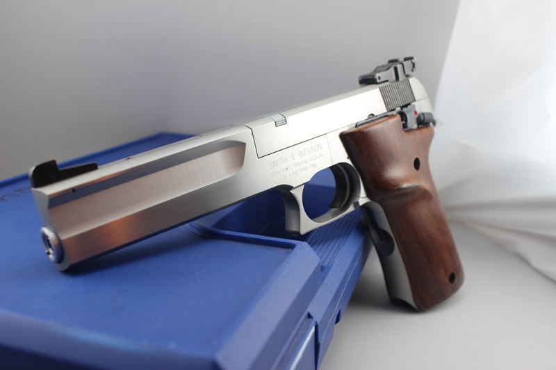
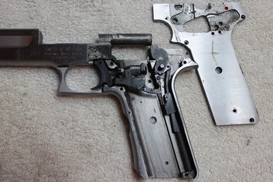
Disassembly - Frame
Step
6: Remove grips
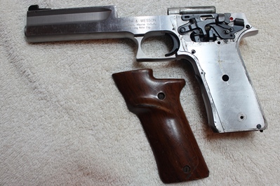 |
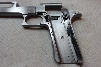
| Grips Removed |
Step
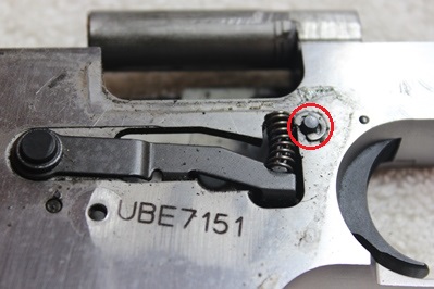
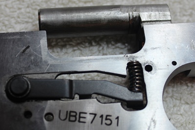
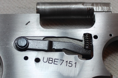
7: Remove slide stop spring
The slide stop spring is the only spring on the left hand lever assembly.
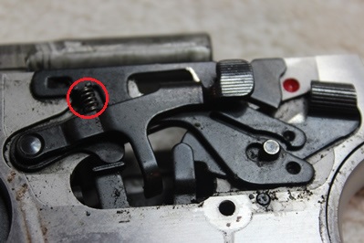 |
| Slide Stop Spring |
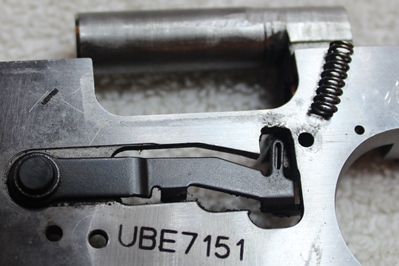
Step
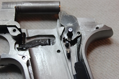
8: Remove C-clip
A screwdriver can be used to either push or pull the C-clip (retaining ring) from the slide stop shaft. Use caution to not scratch the frame.
 |
| C-clip |
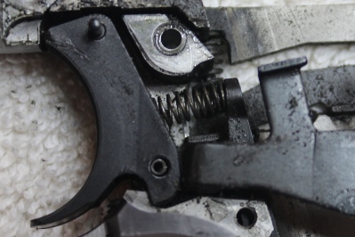
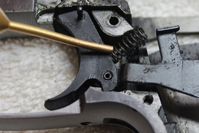
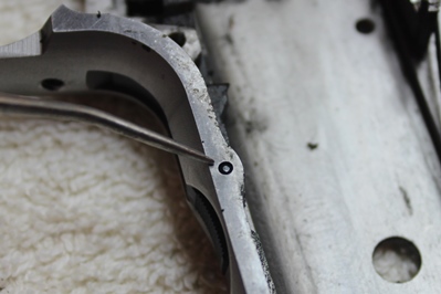
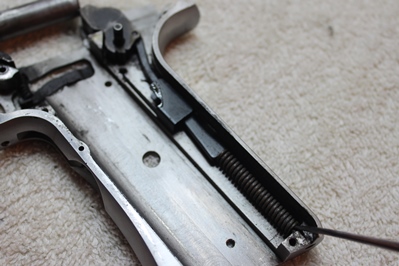
Step
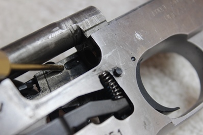
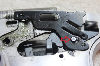
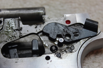
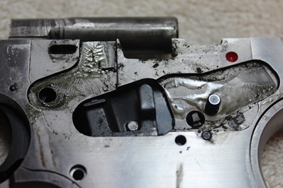
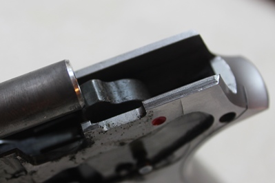
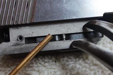
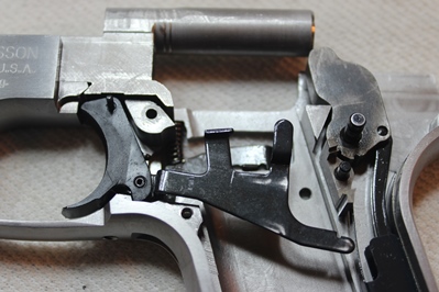
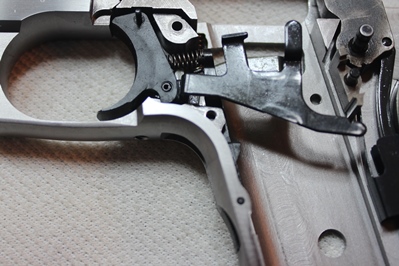
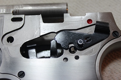
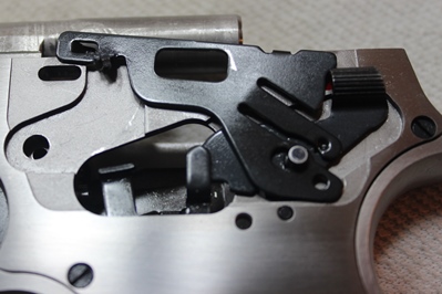
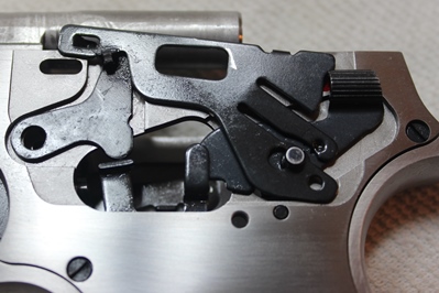
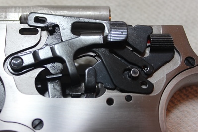
9: Rotate spring plate out of detent
Using a punch, push the detent from its recess and rotate the spring plate so the detent is just above the frame.
 |
|
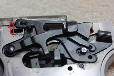 |
| Detent Recess |
|
Detent Positioned Above Frame |
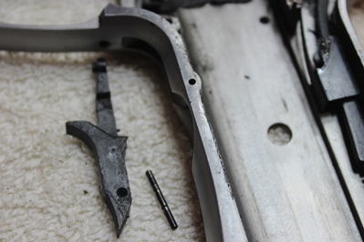
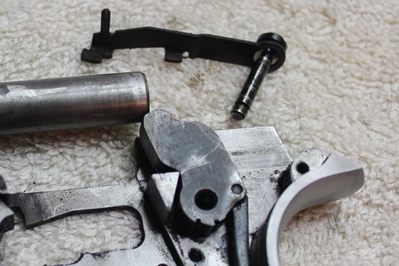
Step
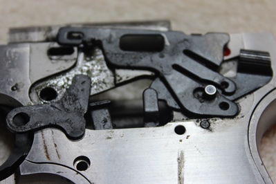
10: Remove slide stop lever
 |
| Slide Stop Lever Removed |
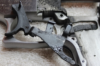
Step
11: Remove disconnector
 |
| Disconnector Removed |
Step
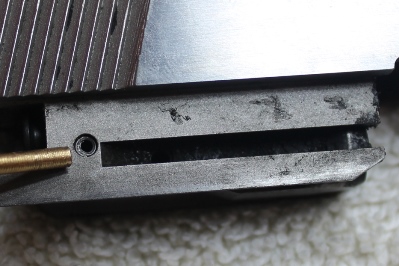
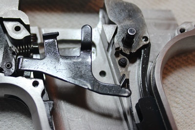
12: Remove spring plate
Move the spring plate rearward until the larger hole aligns with the hammer pivot pin, then remove the spring plate.
 |
| Spring Plate Shifted Rearward |
Step
13: Remove safety lever
 |
| Safety Lever Removed |
Step
14: Insert magazine and release hammer
Insert the magazine into the frame to disable the magazine safety, then restrain the hammer and pull the trigger, slowly release the hammer into the fired position. Remove the magazine.
 |
|
 |
| Insert Magazine |
|
Magazine Safety Disengaged |
| |
 |
|
 |
| Hammer In Cocked Position |
|
Hammer In Fired Position |
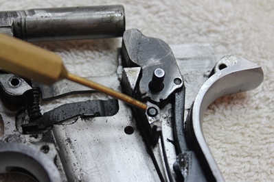
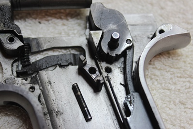
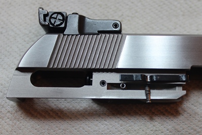
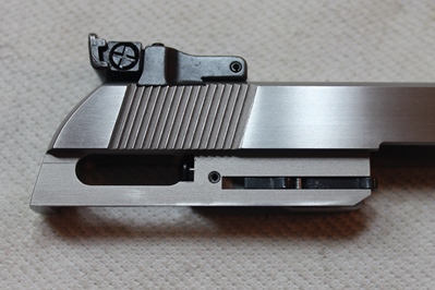
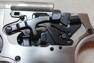
Step
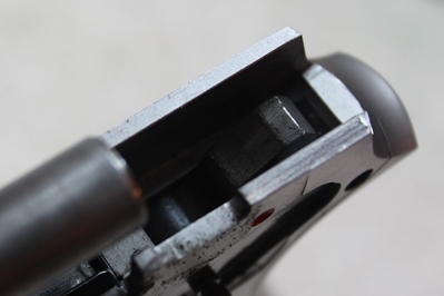
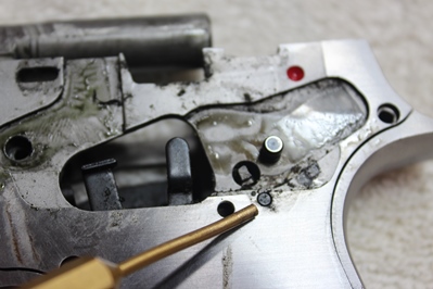
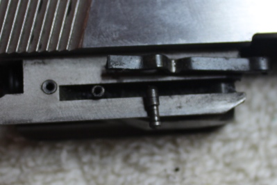
15: Push sear pin out of out of sideplate
Using a punch, push the sear pin about a 1/8th of an inch so that it no longer is engaged in the sideplate. Do not push the pin completely out of the frame.
 |
|
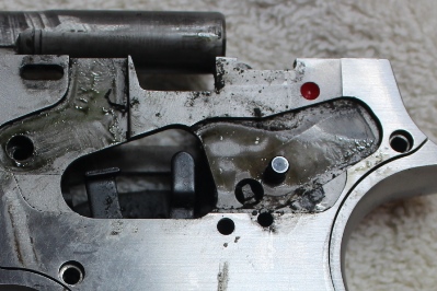 |
| Sear Pin Engaged In Sideplate |
|
Sear Pin Pushed In 1/8 Inch |
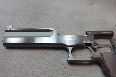
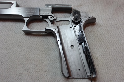
Step
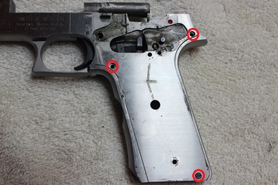
16: Remove sideplate
Remove the three screws that hold on the sideplate, then lift the sideplate from the frame. Try to lift the sideplate equally, rocking it back and forth if necessary to get it to release from the frame. Restrain the trigger so that it does not come off with the sideplate.
 |
|
 |
| Remove Three Sideplate Screws |
|
Sideplate Removed |
Step
17: Remove trigger/magazine catch spring
 |
|
 |
| Trigger/Magazine Catch Spring |
|
Trigger/Magazine Catch Spring Removed |
Step
18: Remove trigger assembly
 |
| Trigger Assembly Removed |
Step
19: Remove magazine catch
Push out the magazine catch pin with a dental pick or toothpick and remove the magazine catch.
 |
|
 |
| Magazine Catch Pin |
|
Magazine Catch Removed |
Step
20: Remove sear
Push out the sear pin with a punch and remove the sear.
 |
|
 |
| Sear Pin |
|
Sear Removed |
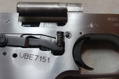
Step
21: Remove magazine safety spring
 |
|
 |
| Magazine Safety Spring |
|
Magazine Safety Spring Removed |
Step
22: Restrain hammer spring
Move the hammer slightly rearwards until a dental pick can be inserted into a small hole at the bottom of the hammer strut. Once the dental pick is engaged, the hammer can be allowed to move back forward. This compresses the spring on the strut allowing the hammer assembly to be removed.
 |
| Dental Pick Engaged On Hammer Strut |
Step
23: Remove hammer pivot pin and magazine safety
Push/pull out the hammer pivot pin.
 |
| Hammer Pivot Pin Removed |
Step
24: Lift out hammer assembly and sear spring
The hammer assembly can be further disassembled by pushing out the pin that holds the hammer to the strut.
 |
| Hammer Assembly, Hammer Spring, and Sear Spring |
Step
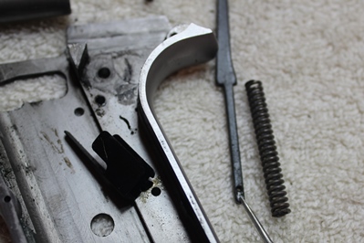
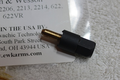
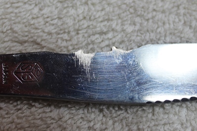
25: Purchase or fabricate tool for removing barrel nut
If fabricating a tool make sure it clears the muzzle.
 |
|
 |
| EWK Arms Barrel Nut Removal Tool |
|
Dremeled Butter Knife |
Step
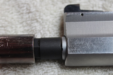
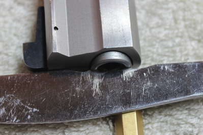
26: Using tool remove barrel nut and lock washer
 |
|
 |
| Barrel Nut Recesses Engaged (EWK) |
|
Barrel Nut Recesses Engaged (Butter Knife) |
| |
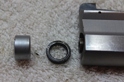 |
| Barrel Nut and Lock Washer Removed |
Step
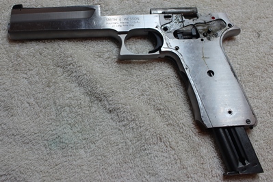
27: Remove barrel from frame
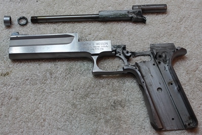 |
| Barrel Removed |
Disassembly - Slide
Step
28: Remove extractor
Push the extractor inwards just behind the extractor pin to disengage the extractor from the extractor pin. The extractor pin is not press fit, but it does need help to move it down out of the slide, use a small pair of tweezers or similar tool to grasp the shaft of the pin to assist it out the bottom of the slide. Note: This 2206TGT only uses one spring beneath the extractor, other models may use two.
 |
|
 |
| Extractor Assembled |
|
Extractor Pin Moved Halfway Out (Tools Shown) |
| |
 |
| Extractor Disassembled |
Step
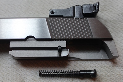
29: Remove firing pin
Using a punch, drift out the roll pin that retains the firing pin. Once removed, pull the firing pin and spring out the rear of the slide.
 |
|
 |
| Firing Pin Retainer Roll Pin |
|
Firing Pin Removed (Firing Pin Shown Upside Down) |
Disassembly - Magazine
Step
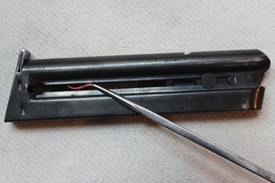
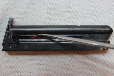
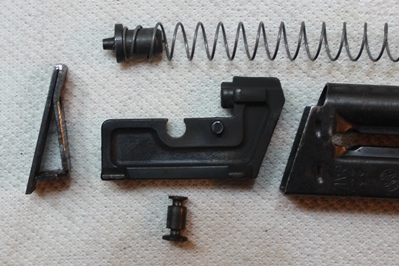
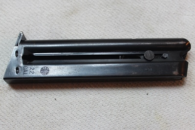
30: Compress magazine spring
Using a dental pick or similar tool, hook the magazine spring through the slot that runs the length of the magazine body, and compress the spring towards the follower. This will disengage the plunger that retains the magazine butt plate. The spring can be held in this position for the next step, or a make-shift stopper can be inserted into the magazine body to keep the plunger from reengaging the butt plate.
 |
| Magazine Spring Compressed |
Step
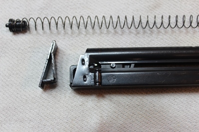
31: Remove magazine base plate
While restraining the plunger above the butt plate, slide the butt plate forward off the magazine body. If the butt plate is being stubborn, the forward edges can be gripped with pliers and pulled forward; pad the plier jaws with electrical tape to prevent any marring.
 |
| Butt Plate Moved Halfway Off The Magazine Body |
Step
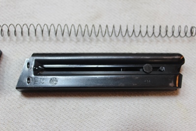
32: Remove magazine spring and plunger
With the butt plate removed, pull the spring and plunger out of the magazine body.
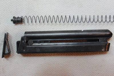 |
| Magazine Spring and Plunger Removed |
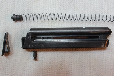
Step
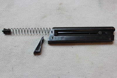
33: Remove magazine follower
Slide the follower down the magazine body until the magazine pin aligns with the round cutout in the slot. Pull out the magazine pin and remove the follower out the bottom of the magazine body.
 |
|
 |
| Magazine Pin Aligned With Cutout |
|
Follower Removed |
Reassembly - Magazine
Step
34: Install magazine follower
Insert the follower into the magazine body and align the magazine pin holes with the round cutout in the slot. Insert the magazine pin and slide the follower to the top of the magazine body.
 |
|
 |
| Magazine Pin Hole Aligned With Cutout |
|
Follower Installed |
Step
35: Install magazine spring, plunger, and butt plate
Insert the magazine spring and plunger into the magazine body. Compress the spring towards the follower and slide on the butt plate. Caution: The spring can eject out of the magazine body with high velocity if it is released before the butt plate is installed. The butt plate may require minor tapping to get it to fully seat onto the magazine body.
 |
|
 |
| Magazine Spring and Plunger Inserted In Magazine Body |
|
Butt Plate Installed |
Reassembly - Slide
Step
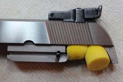
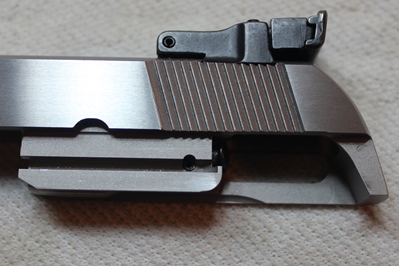
36: Install firing pin
Insert the firing pin and spring into the firing pin cavity; insure the notch on the firing pin is down so the roll pin can be installed. Push the firing pin forward and hold it in place, a pair of earplugs can help restrain it in the forward position. Insert the roll pin into the slide and tap it into place with a punch and hammer, the roll pin should not extend beyond the slide's surface. Test the function of the firing pin; when pressed it should extend out the front, when released it should retract.
 |
|
 |
| Firing Pin Notch Down |
|
Firing Pin Restrained By Earplugs |
| |
 |
| Firing Pin and Roll Pin Installed |
Step
37: Install extractor
Insert the extractor spring in the spring cavity and place the extractor over the spring. Press the extractor down against the spring and push the extractor pin all the way up so the notch in the pin aligns with the extractor. Note: This 2206TGT only uses one spring beneath the extractor, other models may use two.
 |
|
 |
| Extractor Parts Staged For Assembly |
|
Extractor Installed |
Reassembly - Frame
Step
38: Reinstall barrel
Insert the barrel back into the frame, load the lock washer, and screw on the barrel nut. Using the EWK tool you can apply the appropriate torque to the nut (25in-lb recommended by EWK), with a custom tool that is not compatible with a torque wrench you need to snug it down tight.
 |
| Barrel Installed |
Step
39: Reinstall sear spring and hammer assembly
Compress the spring on the hammer strut and hold it in place with a dental pick through the hammer strut hole, this spring is very stiff and compressing it is easier said than done. Place the sear spring and hammer assembly in the frame, align the sear spring tab with the hole in the frame. Keep the spring compressed for the next step.
 |
| Sear Spring and Hammer Placed In Frame |
Step
40: Reinstall hammer pivot pin and magazine safety
Align the hammer with the pivot pin hole in the frame and install the magazine safety and hammer pivot pin. The dental pick can now be removed from the hammer strut.
 |
| Magazine Safety and Hammer Pivot Pin Installed |
Step
41: Reinstall magazine safety spring
Slide the magazine safety spring onto the magazine safety spring guide, and then compress the spring to move it into position against the frame.
 |
| Magazine Safety Spring Installed |
Step
42: Reinstall sear
Align the sear to the hole in the frame, the protruding features of the sear should be pointing away from the frame and the large flat surface of the sear should be aligned with the magazine well. Insure the sear spring is located to the rear of the sear and then install the sear pin.
 |
| Sear Installed |
Step
43: Reinstall trigger assembly
Drop the trigger assembly into the frame inserting the pin at the trigger pivot point.
 |
| Trigger Assembly Installed |
Step
44: Reinstall magazine catch and spring
Place the spring between the trigger assembly and magazine release lever, then align the release lever with the pin hole in the frame and insert the pin. The magazine release lever can be installed before the trigger assembly, but it may be more difficult to install the spring between the two. Installing the spring after both the trigger assembly and magazine catch have been installed can result in a launched/lost spring.
 |
| Magazine Catch and Spring Installed |
Step
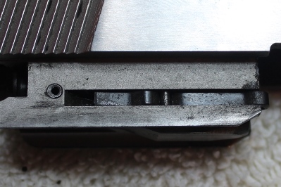
45: Reinstall side plate
Push the sear pin down into the frame so that it will not engage the side plate when it is being installed. Install the side plate by aligning it to the frame cutout as well as the trigger pin and the hammer pin. Push the side plate onto the frame; it may take some light tapping to get it to fully seat in place. Install (3) side plate cover screws and slide the sear pin into the side plate so that it sits flush on both sides.
 |
|
 |
| Sear Pin Pushed Down |
|
Side Plate Installed |
Step
46: Cock hammer
Move the hammer so that it locks back in the frame.
 |
| Hammer Cocked |
Step
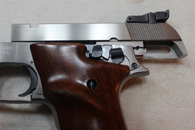
47: Reinstall safety lever
 |
| Safety Lever Installed |
Step
48: Reinstall spring plate
Orient the spring plate so the detent is sitting above the top of the frame and the large hole aligns with the hammer pivot pin. Push the plate down at the hammer pivot pin and slide it forward so that the pin is the smaller hole cut out.
 |
| Spring Plate Oriented and Placed On Hammer Pivot Pin |
Step
49: Reinstall disconnector
 |
| Disconnector Installed |
Step
50: Reinstall slide stop lever
 |
| Slide Stop Lever Installed |
Step
51: Rotate spring plate into position
Insure the spring plate is as far forward on the hammer pivot pin as possible and then lift the forward end of it as required to rotate the detent into the side plate recess.
 |
| Spring Plate Rotated In Place |
Step
52: Reinstall slide stop lever C-clip
Push the C-clip onto the slide stop shaft using a screw driver or flat edge. Use caution to not scratch the frame.
 |
| C-clip Installed |
Step
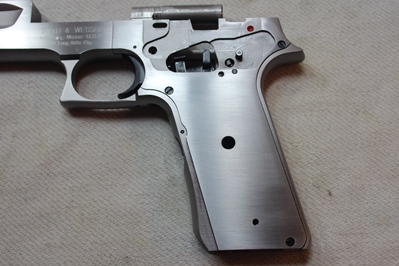
53: Reinstall grips
 |
| Grips Installed |
Reassembly - Field Strip
Step
54: Place slide on frame
Place slide on frame and move it to the rear most position.
 |
| Slide On Frame In Rearward Position |
Step
55: Insert the guide rod and recoil spring
Insert the guide rod and recoil spring into the front of the slide and use the safety takedown flag (or 22LR case) to restrain it in position.
 |
| Slide On Frame In Rearward Position |
Step
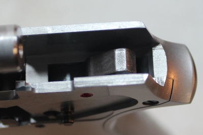
56: Insert the slide plug
Slide the frame forward on the frame and insert the slide plug to restrain the guide rod. Remove the safety take down flag.
 |
| Slide Moved Forward and Slide Plug Ready For Insertion |
2206 Takedown and Reassembly Complete