Timing Belt and Water-Pump Replacement
By skjos
2002 4runner SR5 4WD, 3.4L 5VZ-FE Engine
Date: 01/14/12, updated 06/04/2022 (excluding part/tool costs)
Parts
| Part Name |
Part Number |
Toyota Cost |
OEM Manufacturer |
OEM Cost |
| Timing Belt |
13568-69095 |
$39 |
Mitsuboshi |
$30 |
| Crankshaft Pulley Bolt |
90119-16006* |
$5 |
| Idler Roller |
13505-62040 |
$71 (optional @ 90K) |
NSK |
$31 |
| Tensioner Roller |
13503-62070 |
$95 (optional @ 90K) |
Koyo |
$36 |
| Front Crankshaft Seal |
90311-40022 |
$6 (optional) |
| Front Camshaft Seals (2) |
90311-38051 |
$9 (optional) |
| Hydraulic Tensioner |
13540-62021 |
$33 (optional @ 90K) |
| Water-Pump (w/gasket) |
16100-69398-83 |
$95 |
AISIN |
$52 |
| Thermostat |
90916-03075 |
$16 |
Kuzeh |
| Thermostat Gasket |
16325-62010 |
$5 (comes with water pump) |
| AC Compressor Belt |
99364-20870-78 |
$17 |
Bando/Mitsuboshi |
$9 |
| Alternator Belt |
90080-91090-83 |
$12 |
Bando/Mitsuboshi |
| Power Steering Belt |
90080-91126-83 |
$10 |
Bando/Mitsuboshi |
| Radiator Hose Upper |
16571-62070 |
$13 (optional) |
| Radiator Hose Lower |
16572-62090 |
$13 (optional) |
| Toyota Red Coolant |
00272-1LLAC-01 |
$22 (per gallon) |
| Timing Cover Gasket |
11329-20010 |
$5 |
| Dipstick Tube O-ring |
96721-19010 |
$2 (optional) |
*1996-1998 P/N: 90105-16031
The easiest and least expensive way to get all the parts you need is to buy a kit that includes everything, just verify the kit uses Toyota or OEM parts. There are many kits available on ebay, some more complete than others, whatever the kit might be missing can always be ordered from the dealership.
Tools and Materials
Jack
Jack stands or Ramps
Ratchet
Metric socket set (6pt)
Various socket extensions
Bucket
2.5feet Ľ fuel line (for draining coolant)
Pliers / Channel locks / Needle nose
Shop rags
Plastic bags
Rubber bands
Hose removal hook
Knife / Box cutter
Metric wrenches
14mm ratcheting wrench (for power steering tensioner)
Plug (for dipstick hole if removed)
Breaker bar (˝ drive)
19mm socket (6pt - ˝ drive)
Crank pulley wrench (OTC 4754 - $35)
Marker for old timing belt
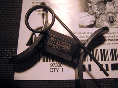
Tensioner tool with pin - if reusing tensioner (Schley SCH97300 - $47)
Seal puller - if replacing crank/cam seals (Lisle 58430)
1 foot of 1.5 inch schedule 40 pvc pipe (to fabricate crank/cam seal pushers)
1.5 inch fender washer (for seal pusher)
Flat head screwdriver (to pry off water-pump)
Gasket scraper or Razor blades
Oil-free non-residue cleaner (acetone)
10mm allen socket
Binder clips (to hold timing belt to cam pully)
Torque wrench (in/lb)
Torque wrench (ft/lb)
Torque wrench (250ft/lb - ˝ drive)
Belt tension gauge (OTC 6673, Borroughs BT-33-73F)
6 inch scale (for measuring belt tension without gauge)
Fluid measuring cup
Distilled water
Links
In 2012 there was really only the 4x4wire write up, now in 2022 there are many more. I've added Timmy The Toolman's video because it is very helpful, but note that the instructions below deviate from both these linked processes.
4x4wire.com Timing Belt Write-Up
Toyota Timing Belt Replacement (PART 1) for 3.4L V6 5VZ-FE (4runner, Tacoma, Tundra & T100)
Note
Torque specifications are per 2002 4Runner Factory Sevice Manual (FSM)
Summary
The following steps document the procedure I used to replace my timing belt and water-pump. I'm sure there are quicker ways to perform this task, but this method will get the job done.
Please follow these steps at your own risk, I am not liable for any damage you may do to yourself or your vehicle.
Disassembly
Step
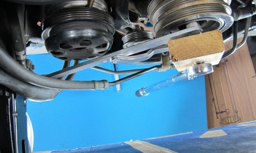
1: Jack-up the vehicle for clearance
Jack-up the front of the vehicle; you will need access from above and below to do this job. You don’t want to go too high because most of the work is done from above, I would say the perfect height would allow your breaker bar and a 250ft/lb torque wrench to clear the ground when loosening/tightening the crankshaft pulley bolt. I just drove onto ramps and then jacked-up the rear end to make it level. Add some lights and you are good to go.
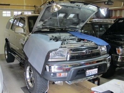 |
| On Ramps With Lights Mounted Above and Below |
Step
2: Remove the negative battery cable
This is a good practice when electrical connections need to be disconnected.
Step
3: Remove the skid plate(s)
Remove the (4) bolts holding on the aft skid plate, then remove the (5) bolts on the front skid plate (all 12mm).
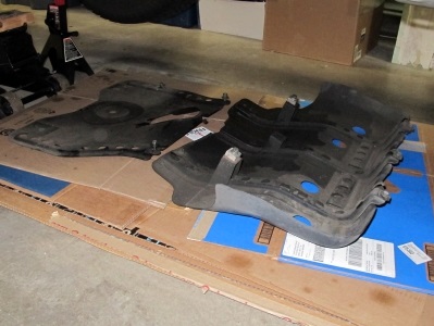 |
| Skid Plates Removed |
Step
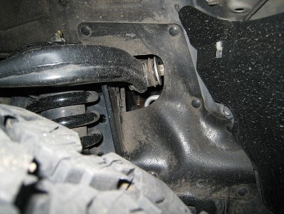
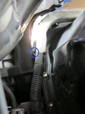
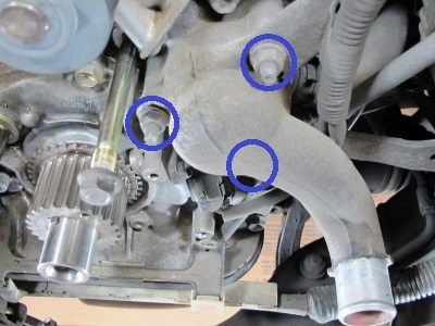
4: Drain the engine coolant
Turn the front and optional rear heaters to hot to open the heater core valves then drain the coolant from the radiator valve and the engine block valve. The engine block drain bolt can be reached by unbuttoning the wheel well skirt on the passenger side of the vehicle and using a couple of long socket extensions. I installed a 1/4” fuel line to the connector (from underneath) and then loosened the 14mm bolt above the port to drain the coolant into a bucket (note the bolt does not need to be removed, just loosened). Once drained close the radiator drain valve and tighten the engine block drain bolt (19ft/lb SS-2 4T). You may as well drain out the coolant from the expansion tank, remove the front battery bracket bolt (12mm), disconnect the hose, pull the tank straight out the top. It may be necessary to tap the tank from underneath to get it to release. After it is drained the tank can be reinstalled, and the battery bracket refastened (10ft/lb SS-2 4T).
Note: You probably don’t need to drain the engine block to do the timing belt, but now's a good time to flush all the coolant.
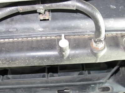 |
| Radiator Drain Valve (transmission hose routing modified to isolate cooler) |
 |
|
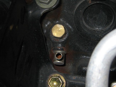 |
| Drain Port from Wheel-Well |
|
Drain Port and Bolt Closeup |
Step
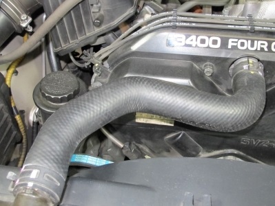
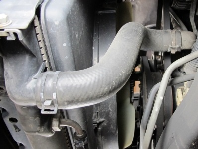
5: Remove the upper and lower radiator hoses
Mark what side of the hose goes to the radiator, they will fit on backwards, and then remove the hoses. My upper hose was tough to remove from the engine, so I ended up cutting it off, making sure not to cut deep enough to scratch the port. A hose removal hook can help, it’s basically a pointy hooked screw driver, but it can easily damage the hose, so I would only use it if the hoses were being replaced. When removing the lower hose from the radiator, have a bucket ready to catch the remaining coolant in the hose. After the hoses have been removed, cover the ports by rubber banding a plastic bag around the hole or by shoving a shop rag in there. Replace the hoses if they are cracked or are no longer pliable.
 |
|
 |
| Upper Hose |
|
Lower Hose |
Step
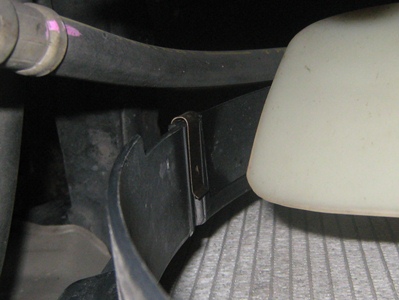
6: Remove the fan shroud
From underneath the vehicle open the clip and remove the transmission hose from the fan shroud. Now disconnect the lower piece of the fan shroud, it is only held on by two metallic clips and a couple plastic tabs. Then remove the (4) 10mm bolts that hold the fan shroud to the radiator, and lift the shroud out of the engine compartment. Tape a piece of cardboard over the exposed radiator to prevent damage during subsequent steps.
 |
|
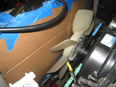 |
| Fan Shroud Clip |
|
Cardboard Protection |
Step
7: Remove the radiator (optional)
The radiator can also be removed at this point to prevent damage and provide more clearance. To remove the radiator, disconnect the transmission lines from transmission cooler at the bottom of the radiator and use vacuum caps to keep the transmission fluid from leaking out. Disconnect the upper coolant line to the expansion tank. Unclip the grill from the (7) locations by pushing the small tab on the clip downward. This will provide access to the (4) 12mm bolts that connect the radiator. Remove the bolts, the radiator will not drop due to a couple hooks holding it on, now remove the radiator from the top. After the radiator is remove protect the AC condenser with cardboard.
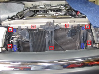 |
| Grill Removed |
Step
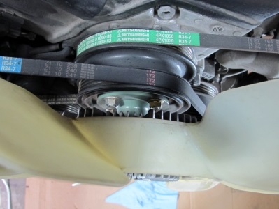
8: Remove the fan (w/fluid coupling)
Loosen the (4) 12mm bolts holding the fan and fan pulleys. With the drive belts still connected you should be able loosen these without the fan shaft moving on you. Remove the fan, and then temporarily reinstall the nuts to keep the pulleys in place Note: it may take a fair amount of wiggling back and forth to get the fan to release.
 |
|
 |
| Fan Nuts |
|
Fan Removed, Nuts Temp Installed |
Step
9: Remove drive belts
Now there is a little more room to work. If you are replacing the drive belts go ahead and cut the old ones off. If you are reusing the drive belts then they will need to be loosened to be removed.
Step
10: Power steering belt removal
Loosen the pivot bolt (14mm). You can get a socket on it through the gaps in the pulley, if the pulley isn’t aligned, just torque the pulley nut clockwise (so you don’t loosen the pulley bolt. The pulley should slide in the belt; if it doesn’t you can always just turn the crank bolt. (the timing marks will be aligned later). Loosen the tension lock nut (14mm). Now loosen the tension on the belt by turning the adjustment bolt (14mm) counterclockwise until the belt can be removed. This bolt can be reached from the front just underneath the pump with a wrench. There is not a lot of room, so the use of a ratcheting wrench is probably the best.
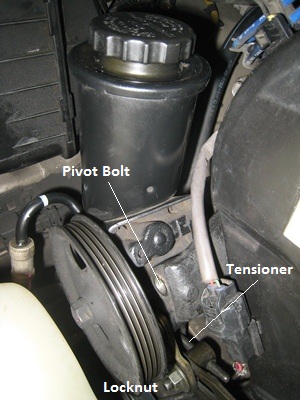 |
| Power Steering |
Step
11: AC compressor belt removal
Loosen the AC adjuster pulley bolt (14mm). Turn the tensioner bolt (14mm) counterclockwise until the belt can be removed.
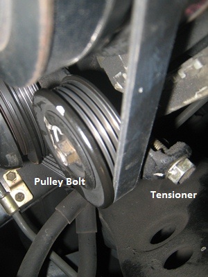 |
| AC Belt |
Step
12: Alternator belt removal
Loosen the pivot bolt (14mm). Loosen the tension lock nut (12mm). Turn the tensioner bolt (12mm) counterclockwise until the belt can be removed.
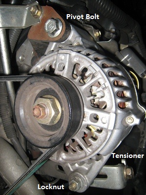 |
| Altenator |
Step
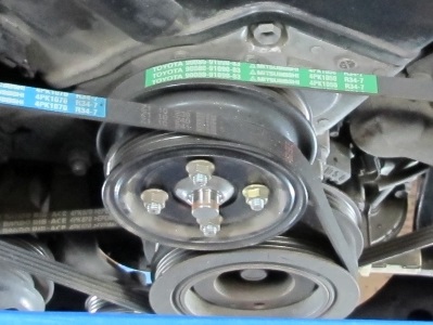
13: Remove drive belt pulleys
Now that the drive belts are removed the fan nuts that hold on the center drive belt pulleys can be removed. The pulleys look like one piece, but they are actually two.
Step
14: Remove the upper timing belt cover
Remove (4) wire clips from along the top of the cover that are supporting the spark plug wires.
Remove the (6) 10mm bolts holding the cover, and pull the cover off to gain access to the backside for removal of the cam shaft positioning sensor. Using needle nose pliers pinch the back side of the connector and push it out of the cover (undoing the electrical connection at this point is not necessary). When I removed my cover the cover-gasket (foam tape) was ripped. This would be a good part to order before you start just in case you need it.
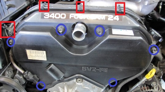 |
| Upper Timing Belt Cover |
Step
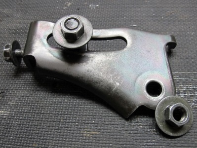
15: Remove the fan bracket
To remove the fan bracket you first have to get the power steering tensioner bracket out of the way. Remove the power steering lock nut and the tensioner bracket nut common to the fan bracket, then remove the tensioner bracket assembly. Now remove the remaining nut and bolt common to the fan bracket (all 14mm).
 |
|
 |
| Fan Bracket Housing |
|
Power Steering Tensioner Bracket Assembly |
Step
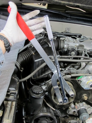
16: Remove the crankshaft pulley
From underneath the vehicle, insert the prongs of the crank pulley wrench into the corresponding holes in the pulley, then wedge the handle of the wrench against the bottom of the driver’s side frame. Now loosen the crankshaft pulley bolt (19mm) with a breaker bar and remove the pulley. While doing this my crank pulley wrench wanted to twist out of the holes in the pulley. To remedy this, I drilled a 1” hole in a short (6”) section of 2x4 and put my socket (with extension) through the hole. When the crank pulley wrench wanted to twist out it would hit the 2x4 which was being held in place by the shaft of my breaker bar. See step 50 for the tool in use when reinstalling the crankshaft pulley bolt.
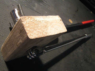 |
| Pulley Wrench with 2x4 |
Step
17: Remove starter wire bracket bolts
The starter wire bracket will get in the way of removing the lower timing belt cover and reaching the tensioner bolt. Remove the two bolts (10mm) and let the bracket dangle.
 |
| Starter Bracket |
Step
18: Remove the lower timing belt cover
Remove the (4) 10mm bolts holding on the lower cover and pull the cover off.
 |
| Lower Timing Belt Cover |
Step
19: Remove the timing belt guide
This is the washer on the crankshaft, while removing it note that the rounded side goes against the timing belt.
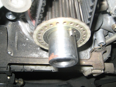 |
| Timing Belt Guide |
Step
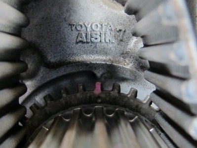
20: Align the crankshaft and camshaft pulleys
Temporarily re-install the crankshaft pulley bolt to rotate the crankshaft to the proper position. Turn the crankshaft (clockwise) until it aligns with the mark behind it, and the two camshaft pulleys align with the marks behind them. If the camshaft pulleys are not aligned, turn the crankshaft one more revolution. This will lightly torque the crankshaft pulley bolt back onto the shaft, to get it off use the pulley removal tool and restrain one of the camshaft pulleys, and then loosen the crankshaft bolt. You will probably get a little movement causing misalignment of the marks, to make minor adjustments turn the camshaft pulley to get everything aligned again.
 |
| Crank Alignment |
 |
| Cam Alignment |
Step
21: Mark the old timing belt and remove it
Mark the belt at the crankshaft and camshaft pulleys (optional). These marks can be used to verify the marks on your new belt are in the proper position. The belt can now be cut off, or if you want to keep the belt intact, the tensioner can be removed and then the idler roller can be removed (see step 23 or 44) and the belt can be taken off.
Step
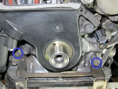
22a: Remove the timing belt tensioner
Remove the (2) 12mm bolts connecting the timing belt tensioner, one is easy to get to the other is a bit more difficult. The latter bolt can be reached using a 12mm socket on a swivel adapter that has been electrical taped to reduce its floppiness, with approximately a foot long extension. Insert the socket extension from underneath between the oil pan and the bracket that holds the A/C tensioner pully, pushing the starter wire housing out of the way as necessary. Try to remove the bolts evenly at the same time, so the tensioner is less likely to bind at an angle. A 1/4" drive socket and extension will provide more clearance for this task.
 |
| Tensioner Bolt (the bolt is removed in this picture) |
Step
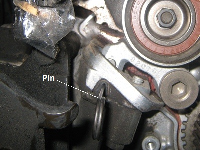
22b: Compress the timing belt tensioner
Compressing the tensioner is probably the better option if the existing tensioner is not being replaced. Install the tensioner tool between the water-pump pulley and the tensioner roller. Turn the hex surface on the tool to compress the tensioner until the pin can be installed through hole in the tensioner. This should be done slowly, like one turn per every five seconds to prevent damage to the tensioner. The pin hole is in a little rubber dust seal; make sure you get the pin all the way through the tensioner before you remove the tool.
Tensioner Tool Instructions
 |
|
 |
| Tensioner Tool |
|
Tensioner Pin Installed |
Step
23: Remove the idler and tensioner rollers
This step is optional, if you are replacing the rollers then both can be removed, if you are replacing the camshaft seals the idler roller will need to be removed. I replaced both rollers for good measure, but it probably doesn’t need to be done if they rotate freely and there is no perceived roughness. To remove the idler roller, unscrew the bolt (14mm) from the center of the roller; to remove the tensioner roller, unscrew the 10mm allen mounting bolt. Note: there is a washer on the backside of the tensioner roller mounting bolt.
Note: The idler roller will be removed to install the timing belt in step 44.
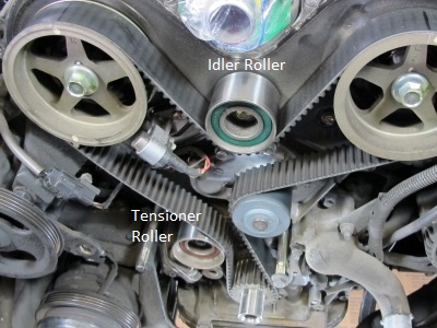 |
| Idler and Tensioner Rollers (the belt would have been removed at this point) |
Camshaft and Crankshaft Seals (optional)
Steps 24 thru 33 are necessary to remove and replace the camshaft and crankshaft seals, these steps are optional when performing the timing belt / waterpump replacement.
Step
24: Remove the camshaft pulleys
Remove can shaft pulley bolts (17mm), restrain the pulley with a pulley holder and then remove the bolts, if the pulleys move, they can be re-centered after the bolt is off. Note: align the pulley holder and the breaker bar close to one another and then use your hand (or two) to grip them together.
 |
| Grip Technique for Removing Camshaft Bolts |
Step
25: Unfasten the camshaft sensor
Remove the one 10mm bolt and take off the cam shaft sensor. It is easier to leave the sensor clipped to the cover, just disconnect the electrical connection and the sensor will come out when the cover is removed.
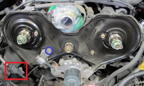 |
| Camshaft Sensor |
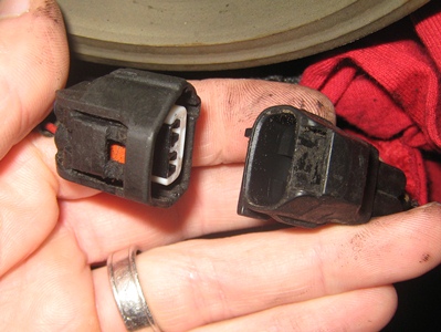 |
| Camshaft Sensor Connector |
Step
26: Remove the inner timing belt cover
Remove (6) 10mm bolts and disconnect the plastic wire bundle housing that is above the left camshaft. Lift the inner cover off of the engine.
 |
| Inner Timing Belt Cover (the camshaft sensor would have been disconnected at this point) |
Step
27: Clean everything
With a majority of the components removed, but the sensitive areas behind the seals, waterpump, and thermostat housing still covered, it is a good time to clean the area for the eventual reassembly.
Step
28: Remove the camshaft seals
Remove the cam shaft seals using a seal puller; Lisle 58430 “Shaft Type Seal Puller” is about the best tool you can get for this job. Clean the shafts after the seals have been removed. Remove and replace the seals one at time so you can compare the seal depth during installation..
 |
| Seal Puller |
Step
29: Install new camshaft seals
Oil the inside of the seal and the outside of the shaft and then push the seal onto the shaft until it reaches the head. Now install your custom 1.5 Dia schedule 40 PVC seal pusher, which should be cut to about 15/16 to 1 inch long (ensure cuts are straight). Put large fender washer on the end and use your camshaft bolt to push the seal on by tightening the bolt. The seal should be flush with the head (the bottom half of the seal interface). See step 31 for a picture of a similar seal pusher.
Step
30: Remove the crankshaft seal
Slide off the crankshaft timing belt gear and remove the crank shaft seal using the seal puller. Clean the shaft after the seal has been removed..
 |
| Crankshaft Seal Removed |
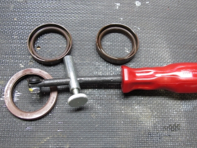
Step
31: Install new crankshaft seal
Oil the inside of the seal and the outside of the shaft and then push the seal onto the shaft until it reaches the housing. Now install your custom 1.5 Dia schedule 40 PVC seal pusher, which should be cut to about 3.25 to 3.5 long (ensure cuts are straight). Use the old crankshaft bolt with the captured washer to push the seal on by tightening the bolt. The seal should be flush with inside chamfer of the housing. Slide the crankshaft timing belt gear back onto the crankshaft after the seal is installed.
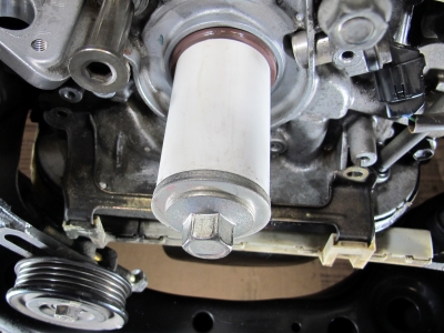 |
| Crankshaft Seal Pusher |
Step
32: Reinstall the inner timing belt cover and camshaft sensor
Relocate the inner timing belt cover and reattach wiring bracket to the upper lefthand side. Then install the (6) 10mm bolts (80in-lb EM-59). Also install the camshaft sensor with one 10mm bolt (71in-lb EM-59).
|
| Inner Timing Belt Cover (the camshaft sensor would have been disconnected at this point) |
Step
33: Reinstall the camshaft pulleys
Restrain the pulleys using the pulley holder and torque the (2) 17mm bolts to (81ft-lb EM-19). Again, use the grip squeeze technique to make this easier (see step 24). If the camshafts come out of alignment use the pulley holder to reclock them.
Water-Pump and Thermostat
Step
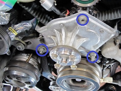
34: Remove the thermostat housing
Remove the (3) 12mm nuts that hold the thermostat housing to the water-pump.
 |
| Thermostat Housing |
Step
35: Unfasten the dipstick tube
To remove the water-pump the dipstick tube needs to be moved out of the way, but it does not need to be taken off. Remove the 10mm bolt holding the upper part of the dipstick tube to the engine, this will provide enough room to take the water-pump off. If you choose to remove the tube just wiggle the tube back and forth until it comes out of the pan. Make sure the hole that goes into the oil pan is covered (rubber stopper); coolant will drain into this area when the water-pump is removed.
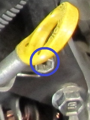 |
| Dipstick Tube Bolt |
Step
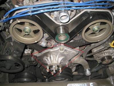
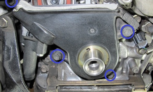
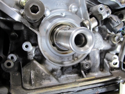
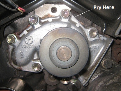
36: Remove the water-pump
Disconnect the oil cooler hose (to the right of the thermostat), then remove the (7) 12mm bolts that hold the water-pump to the engine, now pry off the water-pump. To get the pump off without damaging the mating surfaces, pry on the area of the water-pump that extends beyond the mating surfaces at approximately the 1 o’clock position. Note: The oil dipstick needs to be moved at this point to allow the oil cooler port to clear when the pump is removed.
 |
| Water-Pump |
Step
37: Clean the water-pump mating surfaces
Using a gasket scraper or razor blade, clean the water-pump mating surface on the engine side. Once the surface is clean do a final wipe down with an oil-free non-residue cleaner (I used acetone). Also wipe down the mating surface of the new water-pump.
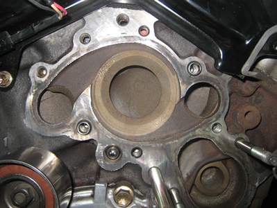 |
| Water-Pump Interface |
Step
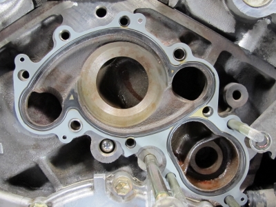
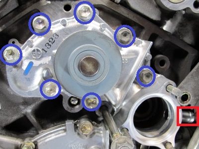
38: Install the new water-pump and gasket
Locate the water-pump gasket to the engine surface; there are some protruding alignment dowels that you can hang it on. Then align the water-pump to the hole pattern and install the (7) 12mm bolts (14ft-lb CO-8). Reconnect the oil cooler hose.
Note: The new water-pumps come with a metal/rubber gasket and no sealant groove, so no FIPG is required. From what I’ve heard, the Toyota mechanics were having problems with installing too much FIPG and damaging engines, so Toyota switched to a gasket to solve this issue.
 |
|
 |
| Water-Pump Gasket |
|
Water-Pump Installed |
Step
35: Refasten the dipstick tube
Reinstall the 10mm bolt holding the upper part of the dipstick tube to the engine (71in-lb EM-22). If the dipstick was removed, verify the o-ring is still attached and in good condition, then coat it with clean engine oil, and snake the tube back into the oil pan and install the bolt.
|
| Dipstick Tube Bolt |
Step
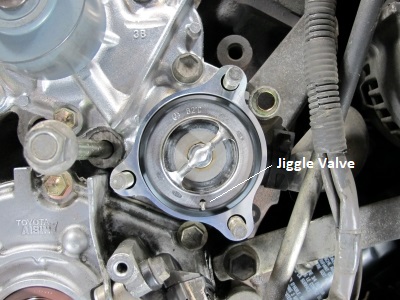
40: Install the thermostat, gasket, and housing
Locate the gasket around the edge of the thermostat and place the thermostat into the water-pump. Make sure to orientate the thermostat with the jiggle valve downward (6 o’clock). Then locate the thermostat housing to the water-pump, be careful that the jiggle valve is not stuck against the mating surface of the housing. Install the (3) 12mm nuts (14ft/lb CO-12). Ensure to fasten the wiring bracket on the outside of the housing at the upper most nut location.
Note: My new water-pump included the thermostat gasket; you may not need to purchase a separate one.
 |
|
|
| Thermostat (jiggle valve at 6 o'clock) |
|
Thermostat Housing Installed |
Installation
Step
41: Perform inspections and cleaning
Prior to installing the timing belt, the new belt should be inspected for any discrepancies, the camshaft and crankshaft seals should be inspected for leaks (look for oil behind the timing cover backing plate), and the idler & tensioner roller should be inspected to verify they rotate freely without any roughness. Clean the area as much as possible, the belt is not supposed to be contaminated with any oil or coolant.
Step
42: Install the timing belt tensioner
If the tensioner was removed rather than compressed, reinstall it with (2) 12mm bolts (20ft-lb EM-21). The inner bolt will need to be reached from underneath again, which is easier to get started using a 1/4" drive socket for clearance through the small gap.
Caution: before installing the tensioner, make sure the pin restraining the tensioner piston is not protruding beyond the backside of the tensioner housing.
 |
|
|
| Tensioner Installation (bolts not fully tightened in picture) |
|
Inner Tensioner Bolt Location |
Step
43: Install the new tensioner roller
If you removed the tensioner roller reinstall it now, ensuring that the washer is placed behind the assembly against the engine, 10mm allen head (26ft-lb EM-19).
Note: The service manual graphic shows 30ft-lb (EM-12), but the service manual text calls-out 26ft-lb (EM-19). Go with the lighter torque here, the linked video stripped the threads at 30ft-lb.(1:06:47)
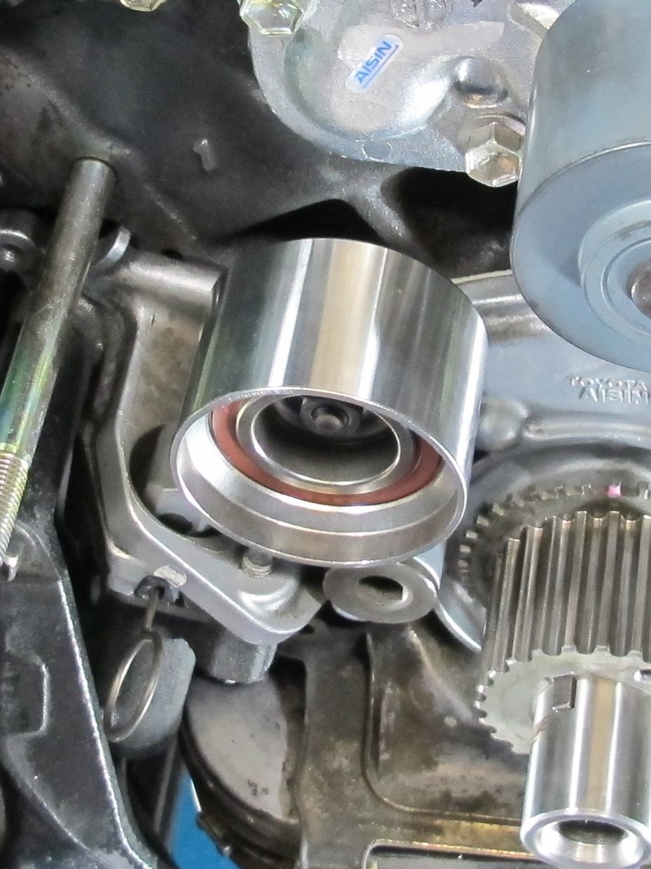 |
| Tensioner Roller Installed |
Step
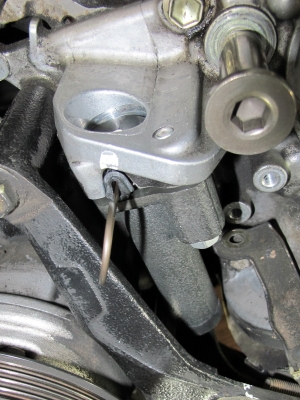
44: Remove the idler roller
The idler roller needs to be removed to get enough slack in the timing belt to install it. To remove the roller, unscrew the bolt (14mm) from the center. This may have already been done in step 21 or 23.
Step
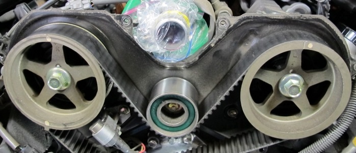
45: Install the timing belt and idler roller
Verify all timing marks are still aligned (cam pulleys and crankshaft), then install the new belt. Line up the RH camshaft belt mark and use a binder clip to hold it in place, then line up the crank belt mark, now pull the belt tight and line up the LH camshaft belt mark and binder clip it in place. Now press the belt down between the two camshaft pulleys with the idler roller and bolt the roller to the engine 14mm (30ft-lb EM-19).
Note: Using clean binder clips to hold the timing belt on the camshaft pulleys helps keep the belt in place while routing it.
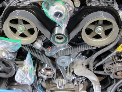 |
| Timing Belt Installed |
Step
46: Remove the tensioner pin
Remove the tool pin that was used to hold the tensioner in the compressed position. Verify the belt timing marks have not moved relative to the timing marks on the pulleys.
|
| Remove Tensioner Pin |
Step
47: Install the timing belt guide
Align the slot on the guide with the slot on the crankshaft; ensure the rounded side is facing the timing belt.
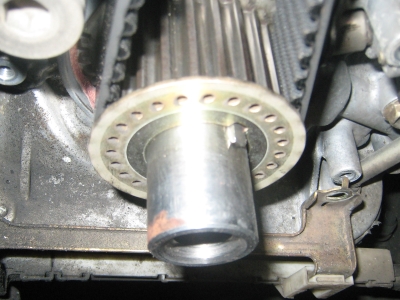 |
| Crankshaft Timing Belt Guide |
Step
48: Install the lower timing belt cover
Re-locate the lower timing belt cover and install the (4) 10mm bolts (80in-lb EM-21).
|
| Lower Timing Belt Cover |
Step
49: Install starter wire bracket bolts
Reposition the starter wire bracket and install the (2) 10mm bolts (69in-lb SS-2 6T).
|
| Starter Bracket |
Step
50: Install the crankshaft pulley
Align the slot on the pulley with the slot on the crankshaft, and install a new crankshaft pulley bolt 19mm (1996-1998: 184ft-lb, 1999-2002: 217ft-lb* EM-22).
Prior to putting the final torque on the bolt you can turn the crankshaft clockwise using the bolt to check the timing. After two clockwise revolutions of the crankshaft all of the pulleys should be realigned with the timing marks. Note that the belt marks will no longer be aligned with the pulley marks, this is normal.
Now for the final torque: from underneath the vehicle, insert the prongs of the crank pulley wrench into the corresponding holes in the pulley, then wedge the handle of the wrench against the bottom of the passenger side frame. Tighten the crankshaft pulley bolt with a torque wrench. Similar to when removing the bolt, my crank pulley wrench wanted to twist out of the holes in the pulley; I used the 2x4 method described in step 16 to remedy this.
Note: I snapped my ˝-3/8 socket adapter while torqueing this bolt, use a ˝ drive socket.
*FSM shows 217ft-lb on EM-12 and EM-22, 213ft-lb on EM-26 and SS-8, and 184ft-lb on CO-4; go with the 217ft-lb torque.
 |
| Crankshaft Pulley Bolt Installation |
Step
51: Install the fan bracket and the power steering bracket
If the small section of fan bracket gasket (foam tape) is cracked or torn, replace it with a new gasket. Then relocate the fan bracket and install the bolt and nut to hold it on (don’t torque them on yet). Relocate the power steering tensioner bracket assembly to the fan bracket and install the nut common to the fan bracket. Torque the fan bracket 14mm bolt and (2) 14mm nuts to (21ft-lb SS-2 4T).
Note: 21ft/lb is based on a 5N (4T) nut type, I'm not sure what the 3 dots on bolt head indicate (dots are typically used for nuts) so I'm treating it as a "no mark" 4T bolt. See FSM page SS-1 thru SS-3.
 |
| Fan Bracket Installed |
Step
52: Install the upper timing belt cover
If the upper cover gasket (foam tape) is cracked or torn, replace it with a new gasket. Thoroughly scrape the old gasket off the cover and the engine and then tape the new gasket onto the cover. Relocate the upper timing belt cover and install the (6) 10mm bolts (80in-lb EM-22). Reconnect the (4) spark plug wire clips to the top of the cover, rejoin the camshaft positioning sensor, and reconnect it to the cover.
|
| Upper Timing Belt Cover |
Step
53: Install the drive belt pulleys and fan (w/fluid coupling)
Relocate the fan belt pulleys and the fan to the fan bracket and install the (4) 12mm nuts (48in-lb EM-23). The fan will want to spin when tightening these bolts, at this point make sure they are on all the way and get them snugged up, final torque will be applied after the belts are installed.
Note: This torque seems low, but is specified in the service manual.
|
| Fan Reinstalled (drive belts installed in next steps) |
Step
54: Install the alternator belt
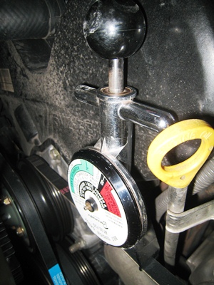
Work the belt around the fan and then around the appropriate pulleys. The tensioner on the alternator will likely need to be loosened to get the belt on (if you cut the belts off, you will need to loosen the pivot bolt and the tensioner locknut). Once the belt is on, turn the tensioner bolt (12mm) clockwise to tighten the belt. The belt should be tightened until the deflection is between Ľ and ˝ inch as measured at the midpoint between the alternator and fan pulley, measure deflection in one direction only. A better way to check tension would be with a belt tensioner tool. Once the belt is at the appropriate tension, tighten the 14mm pivot bolt (38ft-lb CH-6) and the 12mm tension locknut (25ft-lb CH-6).
Belt Tension: New 160 +/-20lbf, Used 100 +/-20lbf CH-3
Belt Tension Gauge Instructions
 |
|
|
| Belt Tension Gauge |
|
Altenator |
Step
55: Install the AC compressor belt
Work the belt around the appropriate pulleys. The tensioner on the AC adjustment pulley will likely need to be loosened all the way to get the belt on (if you cut the belts off, you will need to loosen the pulley bolt). Once the belt is on, tighten the 14mm pulley bolt to 22in-lb AC-18 (this will keep the pulley straight, but still allow it to slide), then turn the 14mm tensioner bolt clockwise to tighten the belt. Because the span between the crank pulley and the adjustable pulley is about 6 inches, the deflection should be 1/4 inch. Once the belt is at the appropriate tension, tighten the pulley bolt (29ft-lb AC-18).
Belt Tension: New 160 +/-25lbf, Used 100 +/-25lbf AC-18
|
| AC Belt |
Step
56: Install the power steering belt
Work the belt around the fan and then around the appropriate pulleys. The tensioner on the power steering will likely need to be loosened to get the belt on. Once the belt is on, turn the tensioner bolt (14mm) clockwise to tighten the belt. The belt should be tightened until the deflection is between Ľ and ˝ inch (for the power steering belt it is probably better to get it close to Ľ inch) as measured at the midpoint between the power steering and fan pulley. Once the belt is at the appropriate tension, tighten the 14mm pivot bolt (32ft-lb SR-41) and the 14mm tension locknut (32ft-lb SR-41).
Belt Tension: New 135-180lbf, Used 85-120lbf SR-3
|
| Power Steering |
Step
57: Apply final torque to the drive belt pulleys
If you couldn’t achieve the proper torque (48in-lb EM-23) in step 53, it should now be possible with the drive belts securing the pulley rotation. The bolts cannot be reached with a torque wrench, but a simple extension makes it possible. I used a 10mm/12mm flare nut wrench, I put the 12mm side on the nut and the 10mm size onto a 10mm allen socket connected to my torque wrench.
Torque extension calculation (if the extension is straight out from the torque wrench)
New torque = specified torque x (torque wrench length / (torque wrench length + extension length)).
- The torque wrench length is measured from the drive head to the middle of the handle.
- The extension is measured from drive head to the center of the fastener.
(Example: New torque = 48in-lb x (9in / (9in + 5in)) = 31in-lb)
If you don’t want to do a calculation, then instead of positioning the extension straight out from the torque wrench, positioned it at 90 degrees and use the specified torque (48in-lb).
Note: This torque seems low, but is specified in the service manual.
|
| Fan Reinstalled (drive belts keep the fan from rotating) |
Step
58: Install the radiator
If the radiator was removed in step 7, it now needs to be reinstalled. Remove the cardboard that was being used to protect the AC condenser and load the radiator from the top and engage the hooks into the body to hold it in place. Then install the (4) 12mm bolts from the front and torque to (105in-lb CO-23). Reinstall the grill by lining up the (7) clip locations and pushing the grill inward until each one clicks in place. Reconnect the expansion tank line to the radiator. Remove the vacuum caps from the transmission lines and reconnect them to the transmission cooler ports.
|
| Grill Removed |
Step
59: Install the fan shroud
Remove the cardboard that was being used to protect the radiator and locate the fan shroud to the radiator. Install the (4) bolts that hold the shroud to the radiator. Reconnect the lower piece of the fan shroud (two metallic clips and a couple plastic tabs). Re-clip the transmission hose to the fan shroud.
Note: The 6T bolt type calls for 69in-lb, but because this is compressing plastic that torque is not valid, I would just tighten until it feels right.
Step
60: Install the upper and lower radiator hoses
Clean the radiator hose ports on the engine and radiator side. Install the hoses using marks you put on in step 4. If you have new Toyota hoses, the engine side is marked with a yellow stripe and the radiator side is marked with a white stripe. With new hoses, make sure to move the clamps from the old hoses onto the new hoses and clock them so that you can expand them with pliers when the hoses are put on.
Note: Wetting the inside of the hose and/or the exterior of the ports with distilled water or coolant can help with slipping them onto the ports. I also hear that water based lubricants, like KY jelly, work well for getting these hoses on.
|
|
|
| Upper Hose |
|
Lower Hose |
Step
61: Fill the engine with coolant
The coolant capacity is 8.5 quarts with no rear heater, or 9.5 quarts with a rear heater. Pour in a gallon of coolant (Toyota red concentrate) and then pour in a gallon of distilled water. The water-pump will mix it up for you. Fill the reaming capacity and expansion tank to the high mark with 50/50 coolant/distilled water. If using prediluted coolant, do not add any distilled water. Squeeze the upper and lower radiator hoses to help get air out, and check for leaks. Install the radiator cap.
Step
62: Start the vehicle and inspect
Take one last look at the engine bay and make sure everything is installed, also verify no tools are sitting where they shouldn’t. Start the vehicle and look for leaks and listen for discrepant noises.
Step
63: Install the skid plates
Locate the front skid plate and install the (5) 12mm bolts (10ft-lb SS-2 4T). Locate the aft skid plate and install the (4) 12mm bolts (10ft-lb SS-2 4T).
Note: my bolt markings were all over the place on the skid plates a mix of 4T, 6T, 7T and 8T, I torqued to 10ft-lb and called it good.
Step
64: Lower the vehicle from the jack stands and road test
Take the vehicle out for a short spin and verify there are no performance problems and listen for discrepant noises.
Step
65: Recheck coolant level and drive belt tension
Once the engine has cooled, add additional distilled water to the radiator and/or the expansion tank if required.
Recheck belt tension and tighted if required.
I hope this helps to provide insight into the timing belt and water-pump replacement process. I would like to thank 4x4wire.com and the Toyota Service Manual for providing a baseline process from which to work from. It also helps to know that if I have any questions, I can always count on yotatech.com for the answers.
|
;)
;)